In today’s digital-first world, high-speed networks depend on the quality and accuracy of their optical fiber connections. Whether supporting 5G deployments, delivering fiber to the home services, or keeping large data centers running efficiently, optical fiber splicing plays a central role in maintaining stable, high-performance communication.
Precise optical fiber splicing reduces signal loss, improves network reliability, and extends infrastructure lifespan. Poor fiber splicing, on the other hand, can lead to performance issues and increased maintenance costs.
This guide breaks down the fundamentals of optical fiber splicing, compares fusion and mechanical techniques, explains factors that influence splice loss, and outlines best practices for protection and testing. It also touches on emerging developments such as AI-assisted splicing tools and bend-insensitive fibers, helping professionals build networks that are robust and ready for future demands.
Understanding Optical Fiber Splicing
Optical fiber splicing represents the permanent or semi-permanent joining of two optical fiber cables to create continuous transmission pathways. This process serves multiple strategic purposes, including extending cable lengths beyond manufacturing limitations, repairing damaged fiber sections, and establishing custom network configurations that accommodate growing bandwidth demands.
The necessity for splicing stems from practical limitations in optical fiber cable manufacturing and deployment. ITU-T Recommendation L.12 establishes that splice performance must maintain stable operation over the system's design life under expected environmental conditions. When properly executed, splicing maintains signal integrity across joined segments while minimizing insertion loss, a critical factor in long-distance telecommunications and high-bandwidth applications.
Primary Splicing Methodologies: Fusion vs. Mechanical Approaches
| Feature | Fusion Splicing | Mechanical splicing |
|---|---|---|
| Typical Loss | 0.1 dB ( can be <0.02dB) | ~0.2–0.75 dB (higher than fusion) |
| Reliability | Permanent decades - long | Semi-permanent may degrade |
| Cost | Higher (equipment-intensive) | Lower (quick repairs) |
| Best Use | Long-haul critical infra | Temporary fixes field repairs |
Fusion Splicing: Precision Through Thermal Bonding
Fusion splicing creates permanent connections by precisely aligning fiber ends and fusing them using controlled heat application. This method produces transparent, non-reflective, and continuous connections between fibers, enabling very low-loss light transmission with typical loss values of 0.1 dB. Modern fusion splicers employ sophisticated alignment systems with core alignment or cladding alignment methodologies.
Technical Performance Metrics:
According to IEC standards for single-mode optical fibers (ITU-T G.652), maximum splice loss specifications are 0.1 dB for fusion splicing. Advanced systems utilizing automated alignment can achieve even lower values, with modern fusion splicers employing sophisticated alignment systems and loss estimators capable of achieving insertion losses lower than 0.02 dB for single-mode fibers.
The fusion splicing process involves two critical alignment approaches:
- 1. Core Alignment Method: This fusion splicing method uses cameras for observation and positioning in two directions, achieving low loss through precise core alignment. This technique offers superior performance for single-mode fibers where Mode Field Diameter (MFD) matching is critical.
- 2. Cladding Alignment Method: This method uses V-grooves produced with high precision to position and orient optical fibers and utilizes the surface tension of melted optical fibers for alignment effects. Recent advancements in fiber production technology have improved dimensional accuracy, making this method increasingly viable for multi-fiber splicing operations.
Advantages and Applications:
Fusion splicing excels in permanent installations requiring maximum reliability and minimal signal degradation. The technique provides superior mechanical strength, typically ranging from 0.5 to 1.5 pounds tensile strength, and offers exceptional environmental stability across temperature ranges from -40°C to 85°C. These characteristics make fusion splicing ideal for long-haul telecommunications, submarine cable systems, and critical infrastructure where splice rework is impractical or impossible.
Mechanical Splicing: Rapid Deployment Solution
Mechanical splicing employs precision alignment devices that hold fiber ends in optical contact using index-matching materials. Mechanical splicing uses small assemblies, about 6cm long and 1cm in diameter, that permanently join two optical fibers with a typical splicing loss of 0.3 dB. While offering higher insertion loss than fusion methods, mechanical splicing provides significant advantages in field repair scenarios and temporary installations.
Performance Characteristics
TIA standards specify a maximum splice loss of 0.5 dB for mechanical splicing of single-mode fibers. The technique introduces higher back reflection compared to fusion splicing but offers considerable flexibility for quick repairs and situations where fusion splicing equipment is unavailable or impractical.
Index Matching Materials:
The most common index-matching materials are silicon gels and silicon greases, which provide superior strain relief and viscoelasticity in the fiber-to-fiber gap, allowing them to accommodate differential thermal expansion and mechanical stresses. These materials minimize optical loss by eliminating air gaps at the splice interface, though their long-term environmental stability requires careful consideration in severe or unusual environmental conditions.
Understanding Splice Loss: Intrinsic and Extrinsic Factors
Intrinsic Parameters: Fiber-Related Characteristics
Intrinsic losses arise from the fiber’s own physical characteristics, set during manufacturing. Among these, Mode Field Diameter (MFD) is the most critical intrinsic parameter influencing splice performance. When fibers with different MFDs are joined, the difference in how each fiber guides light creates a mismatch at the splice point. This mismatch leads to measurable splice loss—typically around 0.035 dB for MFD variations between 8.8 μm and 9.6 μm. Even small deviations in MFD can therefore affect overall network performance, underscoring the need for precise fiber matching in high-quality installations.
Additional intrinsic factors include core diameter variations, numerical aperture differences, and core-cladding concentricity. For general-purpose single-mode fibers, connector/splice loss is calculated roughly as the square of the amount of misalignment multiplied by 0.2, where misalignment by 1 μm at 1310 nm wavelength results in approximately 0.2 dB of loss.
Extrinsic Parameters: Process-Related Factors
Extrinsic losses stem from splicing methodology and execution quality. Splice process parameters include lateral and angular alignment, contamination at the fiber end, and core deformation due to unoptimized heating and pressing. Skilled technicians using properly maintained equipment can minimize these factors substantially.
Observations indicate that splice loss between two identical fibers with the same MFD and geometry parameters can be as high as 0.04 dB due to misalignment and other splicing process parameters.
Critical extrinsic considerations include:
- • Fiber End Angle: Proper fiber end preparation is the most fundamental step to achieve acceptable splice loss, with end angles less than two degrees generally producing acceptable field splice loss
- • Cleaver Maintenance: Well-maintained cleavers typically produce end angles around one-half degree
- • Contamination Control: Proper cleaning procedures and environmental management
- • Alignment Precision: Automated alignment systems significantly reduce operator-dependent variations
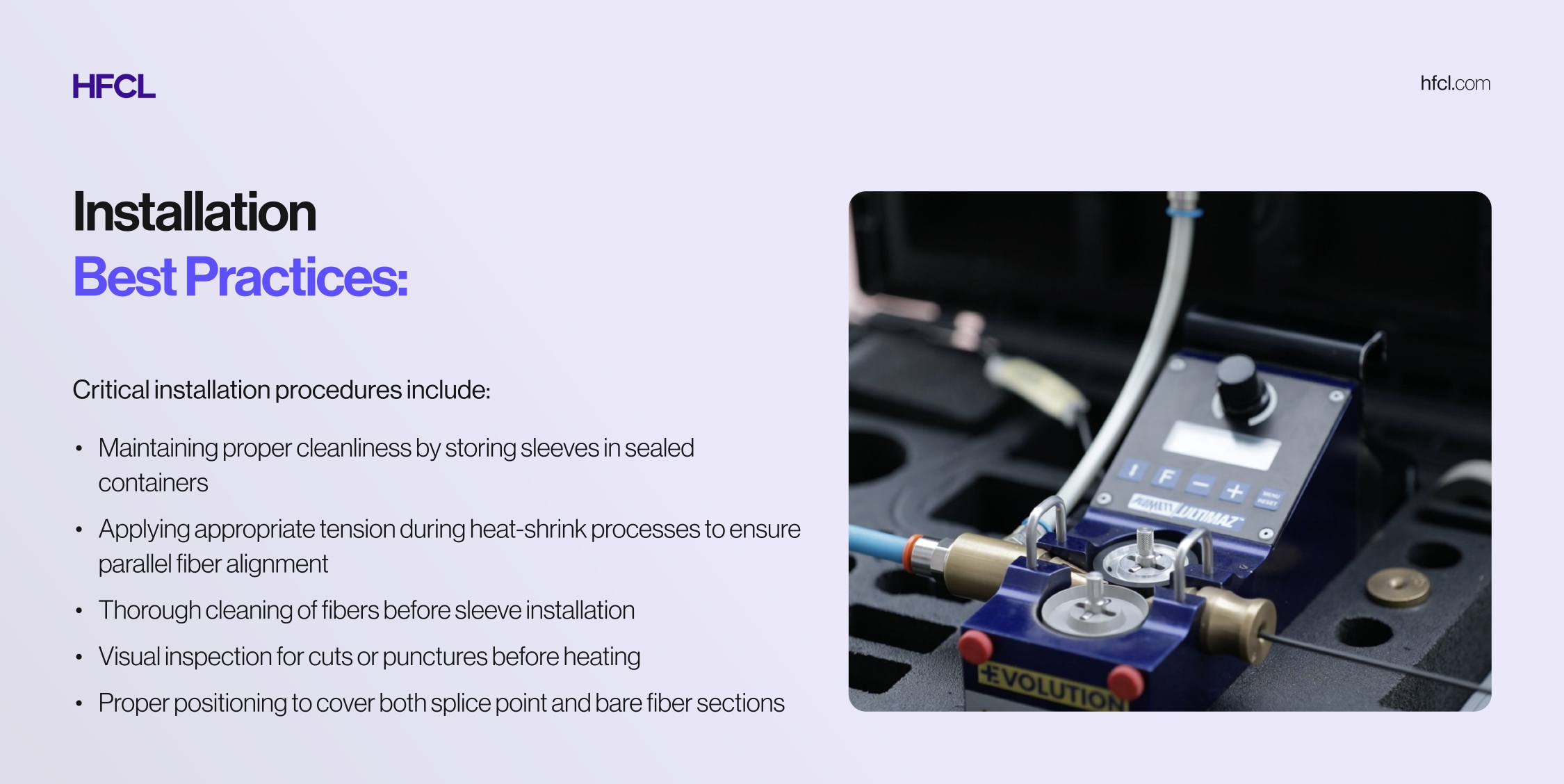
Splice Protection and Environmental Safeguarding
Protecting spliced joints from mechanical stress and environmental hazards ensures long-term network reliability and performance stability.
Splice Protection Sleeves: Standards and Specifications
High-quality protection sleeves comply with Telcordia GR-1380 and IEC 61300-2-42 standards, ensuring durability, optical clarity, temperature stability, and tensile performance under typical network installation conditions. These sleeves typically consist of heat-shrink polyolefin outer tubes, hot-melt adhesive layers, and stainless steel or ceramic reinforcing rods.
Protection Sleeve Categories:
- 1. Single Fiber Protection Sleeves: Designed for single fiber splicing with 60mm length and stainless-steel strength members, these sleeves meet or exceed Telcordia Standard TA-NWT-001380. Common lengths include 40mm and 60mm configurations.
- 2. Ribbon Fiber Protection Sleeves: Specialized designs accommodate multiple fibers simultaneously, typically supporting 4, 8, or 12-fiber ribbon configurations for high-density applications.
Joint Closures: Comprehensive Environmental Protection
Joint closures provide robust protection for spliced fibers against physical damage, moisture ingress, temperature extremes, and environmental contaminants. Closures must comply with standards like ISO 9001:2015 and IEC 61300, confirming quality and environmental safety.
Closure Performance Standards:
Splice closures shall meet requirements per Telcordia GR-771-Core issue-1 document and must be manufactured according to International Quality Standards ISO 9001-2000. These specifications ensure closures withstand diverse environmental conditions, including temperature cycling, humidity exposure, and mechanical stress.
Selection Criteria:
Network designers must evaluate several factors when selecting joint closures:
- 1. Environmental Protection Rating: Protection grade reaches IP68 for closures designed to resist wild environments, intensive climate changes, and serious working conditions.
- 2. Capacity Requirements: Closure capacity must accommodate both current fiber counts and anticipated future expansion needs.
- 3. Cable Compatibility: Key standards include IEC 61300-2-42 for mechanical sealing tests, GR-771-CORE for environmental reliability, and YD/T 814.1-2004 for structural requirements and fiber splice tray compatibility.
- 4. Installation Environment: Aerial, underground, or wall-mounted applications require different closure designs and mounting mechanisms.
- 5. Splice Type Compatibility: Closures must accommodate the specific splicing technique employed (fusion or mechanical).
Quality Verification and Testing Protocols
Ensuring splice quality requires comprehensive testing using specialized equipment and standardized procedures.
OTDR Measurement Methodology
Optical Time-Domain Reflectometers (OTDR) serve as the primary tool for splice loss measurement. As per ANSI/TIA/EIA-455-8-2000 procedure, splice loss measurements with OTDR must be conducted from both directions and averaged for accurate splice loss determination. This bidirectional measurement approach eliminates measurement artifacts such as "gainers" and exaggerated losses that can occur when measuring from a single direction.
Visual Fault Location
Visual Fault Locators (VFL) provide supplementary verification by projecting visible laser light through the fiber, enabling technicians to identify excessive loss points, breaks, and poor-quality splices through visual inspection of light leakage or dark areas at splice points.
Tensile Strength Testing
Final splice approval often includes tensile strength verification to ensure the mechanical integrity of the joint. Properly executed fusion splices should maintain tensile strength near the fiber's proof-test level, typically demonstrating break strengths between 0.5 and 1.5 pounds under controlled testing conditions.
Advanced Considerations and Future Developments
AI-Enhanced Splicing Technology
The integration of artificial intelligence into fusion splicing systems represents a significant advancement in automation and quality assurance. Modern AI-enhanced splicers can predict fiber imperfections, automatically adjust fusion parameters, and achieve first-pass success rates exceeding 99.9%, substantially reducing rework requirements and installation time.
Bend-Insensitive Fiber Compatibility
ITU-T G.657 recommendation specifies bend-insensitive fibers with improved optical performance during bending, with G.657A fibers compatible with G.652D and featuring a specified minimum bending radius of 10mm. When splicing these advanced fiber types, technicians must account for different mode field characteristics that can affect OTDR measurements and splice loss calculations.
Quality Control and Operator Skill Development
Skill disparities yield variable results, with novices potentially incurring 0.4 dB losses versus experts achieving 0.05 dB. Structured training programs and certification processes significantly improve consistency and reduce field failures, making operator development an essential component of network quality management.
Conclusion
As networks continue to scale for next-generation connectivity, a solid understanding of optical fiber splicing techniques has become essential. Fusion splicing remains the most reliable option for high-performance and long-lasting installations, while mechanical splicing still serves as a practical choice for quick field work. Consistency with international standards, thorough testing, and ongoing technician training all play a key role in ensuring long term network performance.
At HFCL, we focus on advancing optical fiber technologies and promoting best practices in deployment. By combining precise engineering with well-executed splicing methods, we help build fiber networks that are robust, efficient, and prepared for future demands.